-
 Lance-Canadafast shipping and no problems
 -
 Lucila-BrazilEquipment of good quality, very responsible seller and fast delivery. I recommend to all Alibaba community / AliExpress. I will definitely buy more units.
 -
 Hamadivo-FranceBest seller,good transaction and fast delivery time
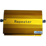
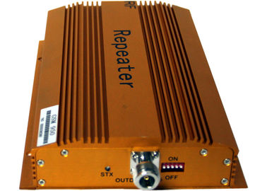
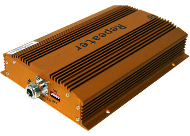
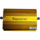
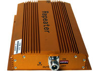
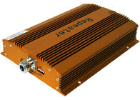
900MHZ Cell Phone Signal Repeater , Indoor Mobile Phone Signal Booster

Contact me for free samples and coupons.
WhatsApp:0086 18588475571
Wechat: 0086 18588475571
Skype: sales10@aixton.com
If you have any concern, we provide 24-hour online help.
x| Product Name | Cell Phone Signal Repeater | Noise Figure | ≤4dB |
|---|---|---|---|
| I/O Impedance | 50Ω/N Connector | Size | 220 X 140 X 40 Mm |
| Coverage Area | 2000 M2 | Pass Band Ripple | ≤3dB |
| Highlight | mobile phone signal repeater,GSM Signal Repeater |
||
900MHZ Cell Phone Signal Repeater , Indoor Mobile Phone Signal Booster
1 Description
A mobile phone signal repeater provides the ultimate solution in any area where cellular communications can not work well due to leak of signals. The repeater device features easy installation & operation, build-in indoor antenna and no interference. It could also improve indoor electromagnetism environments, protract cellular battery life and reduce radiation of cellphones. A mobile phone repeater is ideal for house, home, office use.
2.Futures:
1.Amplify indoor signal of blind area( conference room, hotel, the groud of large building ect)
2. Expand base station signal coverage.
3. Improve the sending and receiving signal coverage.
4. Reduce the radiation of cell phone to human body.
5. Extend the use time and battery of cell phone
6. Easy,hand size and flexible configuration per specific application.
7. Environmental device, small size and low cost.
8. Full-duplex operation, high isolation of uplink and downlink.
9 adopt the dip switch with 2 into the system to control and 2 N power attenuation to select the effective
range.
10. Advanced digital filtering technology and good outside band restraint
11. Economic and reasonable coverage program,high isolution of sending and receiving antenna and no
transceiver interference.
12. Low overflow signal of outdoor and no interference to the sensitivity of base station.
13.Casting integration, fully enclosed shell, beautiful and durable.
3,Installation and debugging
1. installation step
1) use the mobile phone in the tops of the buildings and around to receive signal and check the direction
and location where is strongest receiving and sending signal.To avoid lighting, the installation height can
not higher than the lightning conduction of the building.If the location is higher than lightning conduction,
it needs to install lightning rod which should be higher than the outdoor antenna more than 1m and well
ground.
2) Mount the antenna on the wall or holder after selecting an appropriate position.
3) selecting an appropritae site(it is best site which approach to the power suppler and is away from rain
and sunshine and good ventiltion for outdoor antenna) within indoor related place to install the booster
and fasten it on the wall or holder.
4) connecting the outdoor atnenna with the “OUT DOOR” port and tighen it,then the the connection of the
outdoor antenna and booster is completed.
5) turn off the dip swtich of both side before installation, then turn on the swtiches one by one after
installation
to avoid self-excitation with your local signal and no signal of mobile phone if dip switches are on before
installation.
6) Fix antenna after confrimed the proper installation location of it
7) the cable between the indoor antenna and booster, one end is connected with port of the indoor antenna,
the other end is connected with the“IN DOOR” port of the booster.
2. commissioning
1) properly adjust of the antenna position to make good communication quality and best signal strength.
2) the location of indoor antenna should be far away from outside antenna to avoid causing mutual
interference. (the location outdoor antenna is one floor or more away from indoor antenna, the effect will
be better.)
3) the installation height of indoor antenna should be higher than 2m or reversely install downward
to the ceiling.
4) Wraped the connection place with waterproof tape to avoid reducing the indoor coverage due to moisture.
4 Specification
|
Frequency range |
Uplink:890—915MHZ Downlink 935-960MHz |
|
Gain ( dB) |
Uplink Gp≥50 Downlink Gp≥55 |
|
Export power (Po) |
≥17dBm |
|
Pass band ripple |
≤3dB |
|
I/O impedance |
50Ω/N connector |
|
Noise figure |
≤4dB |
|
Transmission Delay |
≤0.5μs |
|
Ambient temperature |
-10℃~60℃ |
|
Power supply |
AC110~240V 45~55Hz |
|
Size |
220 x 140 x 40 mm |
|
Reliability |
To the GB6993-86 standard |
|
Electromagnetic compatibility |
To the ETS300 694-4 standard
|
|
Function |
a) Power supply LED denote b) Export power LED denote |
|
coverage area |
200 m2 |
5 Pictures
![]()
Picture of company
![]()
Picture of factory
![]()
Picture of fairs
![]()
Picture of certification
![]()


